Aligning a multi-shank probe with a second recording
In this tutorial you will align a four-shank Neuropixels probe, and learn two ways to get more out of your data when aligning.
The first is to look at all four shanks together. The shanks are fixed side by side on the probe and pass through similar anatomy, so a boundary on one shank should appear at a similar depth on its neighbours, and each shank’s alignment is a check on the others.
The second is to bring in another recording. In this session the channels of each shank only cover the bottom 700 µm, too short a stretch to show many boundaries. At the end of the experiment, a short recording was also made with a different channel map, spanning the whole length of each shank. You will load the two side by side and align them together, using the boundaries in the second recording to align the first.
Before you start
Complete Your first alignment. This tutorial assumes you can add reference line pairs and apply a fit.
Extract the Sample data 2 folder from the sample data. It holds two recordings of the same four-shank Neuropixels 2.0 (2.4) probe, in the same session, with 96 channels per shank:
dense: the main recording, with each shank’s channels packed together in its bottom 700 µmsparse: a short recording of about 5 minutes, made at the end of the experiment, with each shank’s channels spread along almost 3 mm
Each shank was spike sorted separately, so each one has its own entry in the session YAML:
probe01atoprobe01d.
1. Open the dense recording
The datasets of Sample data 2 are spread over several folders, so they are listed in a session YAML instead of being opened as one folder. Start with the YAML for the dense recording alone.
Open
sample_data_2_dense.yaml, in the Sample data 2 folder, in a text editor.Change the
pathon the first line to the folder you extracted Sample data 2 into:path: /path/to/ephys_alignment_sample_data/sample_data_2 # <- change this probes: probe01a: datasets: spike_sorting: path: dense/spike_sorting/probe01a raw_ephys: path: dense/raw_ephys/probe01a picks: path: picks/probe01a output: path: dense/alignment/probe01a probe01b: ...
Every other path in the file is relative to this one and so can be left as is. The entries for
probe01b,probe01candprobe01dfollow the same pattern.Save the file.
Start the GUI with the YAML:
alignment-gui -y /path/to/ephys_alignment_sample_data/sample_data_2/sample_data_2_dense.yaml
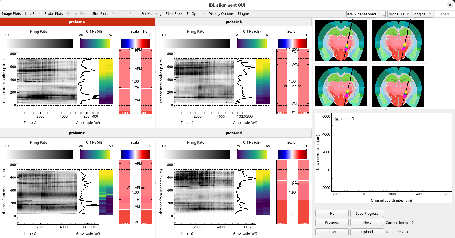
The data loads with the shanks side by side in a grid, each titled with its name. The title of the active shank is red.
2. Switch between the grid and the tabs
Press Right and Left to step through the shanks. The red title moves to show which shank is active.
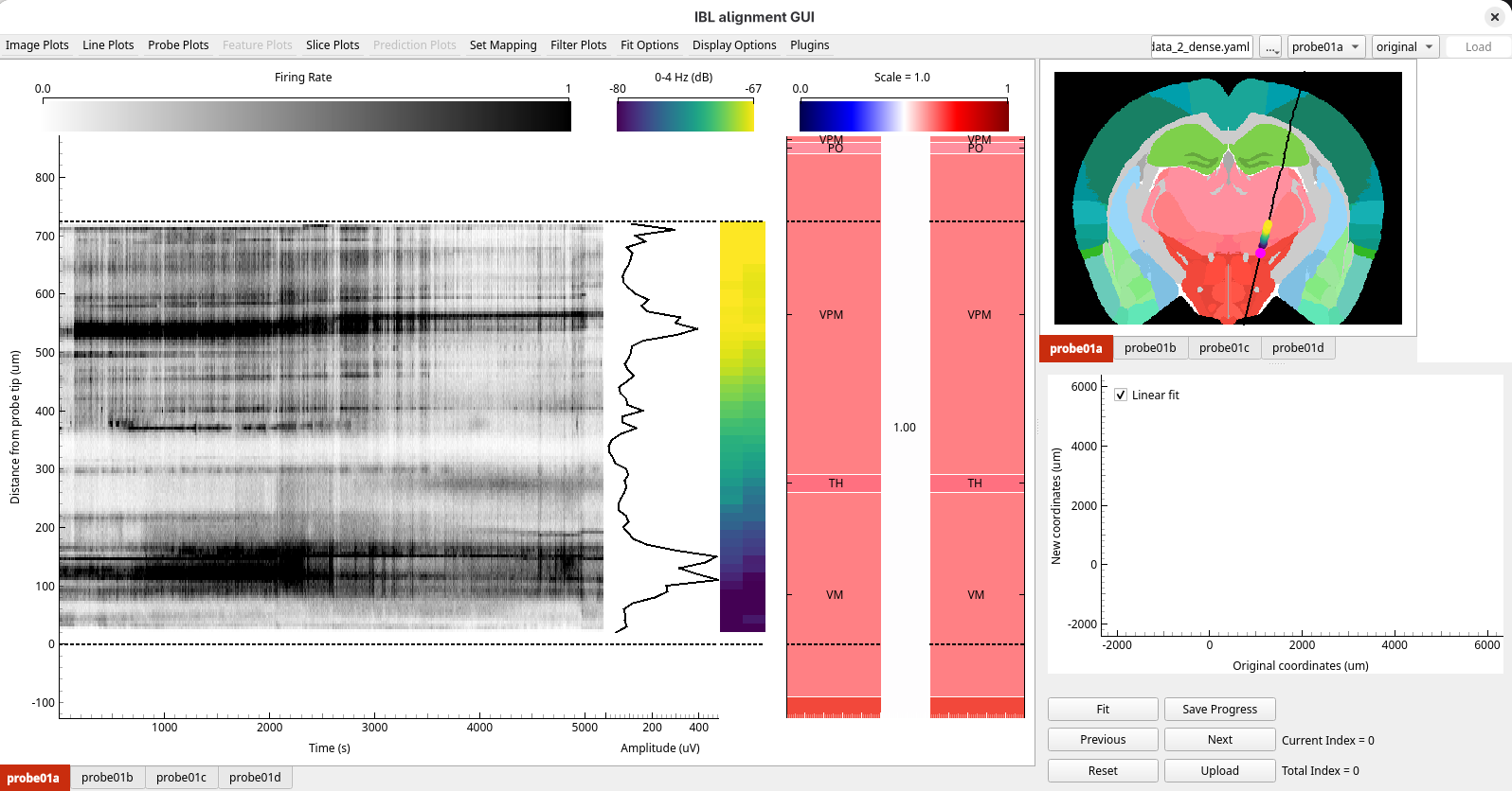
Press T. The layout changes to one tab per shank, and only the active shank is shown.
Press Right and Left again: each press moves to the next tab.
Press T to go back to the grid.
3. Look for landmarks
Cycle through the plots with Alt+1, Alt+2 and Alt+3, as in Your first alignment.
The channels of each shank span only 700 µm, so the probe passes through few regions on this stretch, and few features stand out. There are not enough clear boundaries to align to with confidence.
4. Bring in the second recording
At the end of the experiment, a short recording of about 5 minutes was also made with a different channel map, spanning the whole length of each shank. It is the same probe in the same tissue, so it can be aligned together with the dense recording. The GUI calls each recording a configuration.
The channel map of this recording is the SpikeGLX IMRO table
NPtype2014_quarterDensity_ref1Tip0.imro,
if you want to record with it yourself.
Open
sample_data_2_dense_sparse.yamlin a text editor. It lists both recordings underconfigurations, each with its ownprobes:path: /path/to/ephys_alignment_sample_data/sample_data_2 # <- change this configurations: dense: probes: probe01a: datasets: spike_sorting: path: dense/spike_sorting/probe01a raw_ephys: path: dense/raw_ephys/probe01a picks: path: picks/probe01a output: path: dense/alignment/probe01a probe01b: ... sparse: probes: probe01a: datasets: spike_sorting: path: sparse/spike_sorting/probe01a processed_ephys: path: sparse/processed_ephys/probe01a picks: path: picks/probe01a output: path: sparse/alignment/probe01a probe01b: ...
The
denseconfiguration is the same as the YAML you opened before. Each shank has the same name,probe01atoprobe01d, in both configurations: that is how the GUI knows they are the same shank. Both configurations use the same traced tracks, inpicks, since the probe did not move. Each has its ownoutputfolder, so the results of one do not overwrite the other.Change the
pathand save the file.In the GUI, click
..., choose Open session YAML…, and choosesample_data_2_dense_sparse.yaml.
The data loads, and a configuration dropdown appears in the top right corner, after the alignment
dropdown. It starts on the first configuration in the YAML, dense.
5. Look at the sparse recording
Open the configuration dropdown and choose
sparse. The sparse recording is shown on its own, with the channels of each shank spread along almost 3 mm.Select
Firing Ratefrom theImage Plotsmenu. On every shank the firing stops at about 2000 µm: this probably indicates the boundary between the thalamus and the hippocampus.
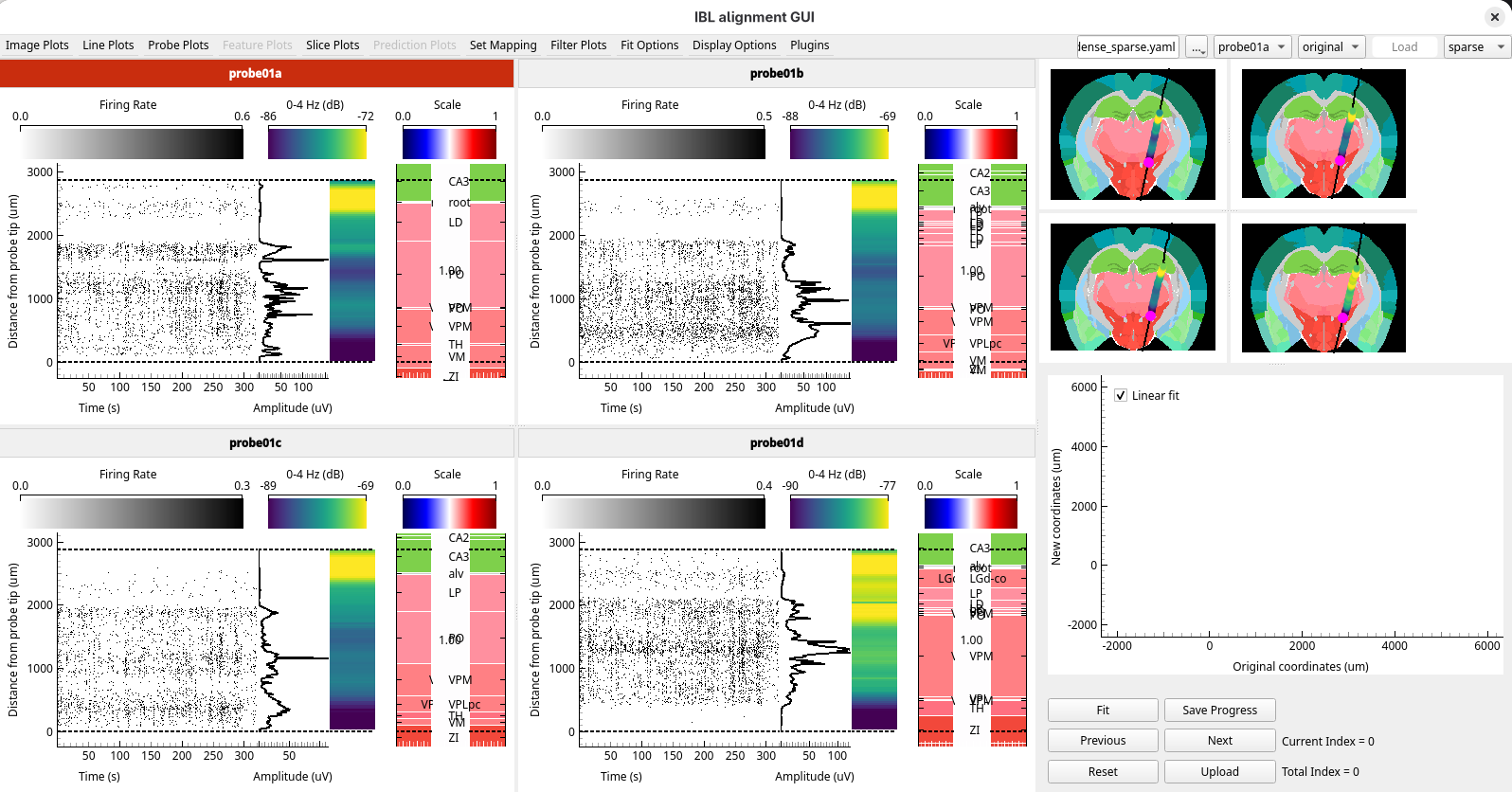
This boundary is well above the dense channels, which stop at 700 µm, so it could not be seen in the dense recording.
6. Show both configurations
Choose
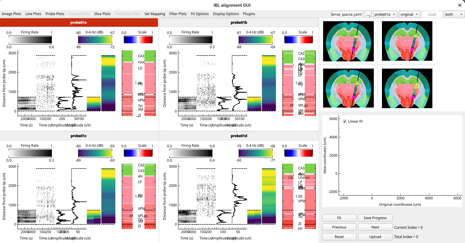
bothin the configuration dropdown. Each panel shows the two recordings next to each other: the dense one in the bottom 700 µm, and the sparse one along the whole shank.
7. Align using the sparse recording
Choose
sparsein the configuration dropdown.On
probe01a, add a reference line pair: the Ephys line where the firing stops, at about 2000 µm, and the Histology line at the top of the thalamus, where the pink thalamic regions meet the green hippocampus.Press Enter to apply the fit.
Do the same on
probe01b,probe01candprobe01d. Press Right to move to the next shank, or double-click in its figures.
8. Compare the shanks
Look at the Fit figure. In the grid layout it shows the fit of every shank.
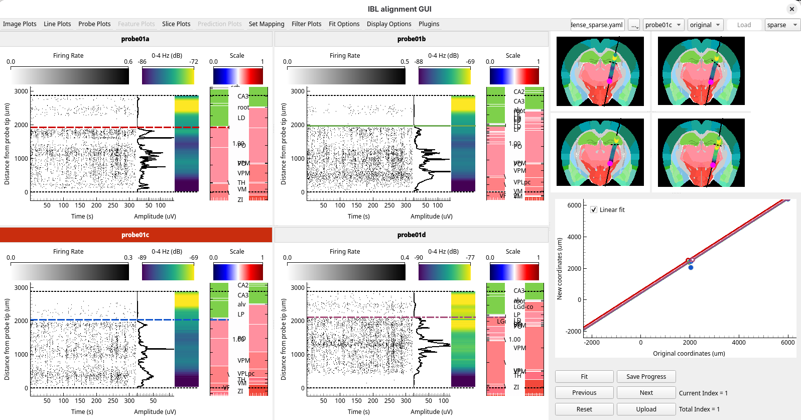
The fits of the four shanks should be offset by similar amounts. The shanks are fixed to the same base, so they are inserted together and cannot move along the track independently of each other. A shank whose fit is offset very differently from the others may be matched to a wrong boundary: check its reference lines against those of its neighbours.
9. See the alignment in both recordings
Choose
bothin the configuration dropdown.
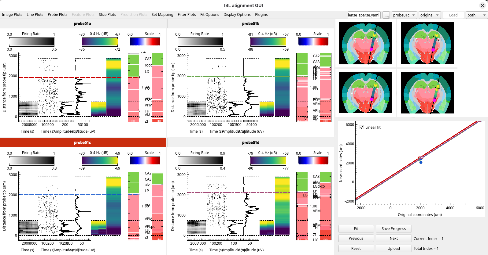
The reference lines you placed in the sparse recording are drawn in the dense one too: the two recordings come from the same probe, so they share one alignment. The fit stretches the histology of both, so the dense channels take their regions from the boundary you found in the sparse recording.
Choose
dense. Its reference lines and fits are the ones you made insparse.
10. Upload the alignment
Press Shift+U or click
Upload. A dialog lists the shanks: tick all four and click OK.Click Yes for each shank.
Open the Sample data 2 folder, and look in
dense/alignmentandsparse/alignment. Each has a folder per shank, and each of those has two new files:prev_alignments.json, which holds the alignment. Open it forprobe01ain bothdenseandsparse: the two are the same, because the recordings share one alignment.channel_locations.json, which holds the position and brain region of every channel. It is different indenseandsparse, because the two channel maps put the channels in different places along the shank.
The alignment you made using the sparse recording now gives the brain region of every channel of the dense one.
What you’ve learned
You have:
looked at the four shanks of a probe together, in the grid and tabbed layouts
combined two recordings of the same probe, and switched between showing one and both
aligned a recording with few landmarks using a boundary in a second recording
used the fits of neighbouring shanks to check each other’s alignment
uploaded one alignment for both recordings, and found the files for each
written session YAMLs with one configuration and with two
Next steps
Shanks, probes and configurations: how shanks, probes and configurations relate
How to compare two versions of a recording: a session YAML with two configurations for your own data